
Airflow Induced Vibration Case Study
We recently got a call from a customer with a vibration problem affecting a highly-advanced production process in a fiber optic manufacturing facility. The customer makes fiber optic strands – tiny glass threads produced by heating and stretching glass tubes into long optical fibers capable of transmitting signals via light over very long distances. Up to hundreds of these optical fibers are bundled into sophisticated data transmission cables designed to transmit vast amounts of information.

The main stranding room is a tightly-controlled environment that utilizes two 30HP direct-drive fans. Dust is filtered and humidity and temperature are closely monitored and managed to avoid destabilizing the process and contaminating the pure glass fibers. The fans in question are housed in a fabricated steel enclosure about half the size of a shipping container, situated above the production room. The fans are approximately 48 inches in diameter and sit side-by-side in the enclosure to push air through the ducting that is approximately four feet square.
The motors driving the twin 30HP fans are mounted to a chassis suspended on vibration isolators that provide more than an inch of static deflection to substantially minimize any vibration being generated. The speed of the fans is controlled by variable-speed AC drives. A series of airflow control devices are used to carefully control the flow of air through the ducts, including sophisticated, adjustable inlet dampers mounted just outside the enclosure on the inlet duct.
Vibration threatens to damage the fan enclosure
The customer was concerned that vibration, seeming to originate in the fans, was threatening to damage the fan enclosures constructed from long spans of sheet metal supported by minimal bracing. According to the facility manager, during full production the fans appeared to be producing significant vibration that was being transmitted into the enclosure walls – enough to cause concern that the enclosure might actually break apart from all the shaking.
Our initial analysis determined that the isolators appeared to be working as intended and that the vibration seemed to be at a much lower frequency than the fan speed – this would indicate that the fans themselves were not the cause of the vibration. Finding the actual cause would require systematically eliminating any possible vibration source to finally determine the true culprit.
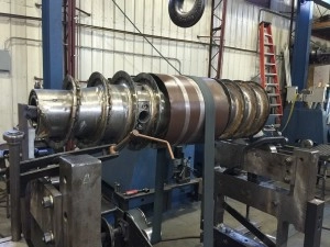
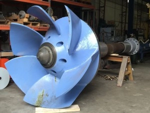
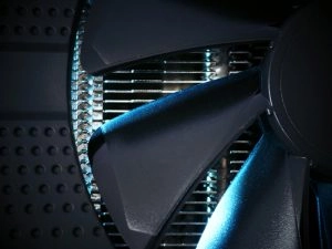
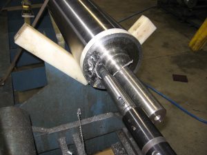
We started by checking the balance condition of the fan wheels and comparing that to industry standards. The fan wheels are aluminum, backward-inclined, airfoil plenum designs with each wheel instrumented with a 4-channel Comtest Vibration analyzer/balancer.
We executed two plane balancing runs and determined that the balance condition of both fans was 5X better than the industry standard of 0.1 inches per second – they were not the source of the vibration.
We now turned our attention to the ducting, dampers, and static pressure gages. Unfortunately, we could not recreate the vibration level experienced during full facility production because parts of the facility were in holiday shutdown and other environmental systems were not running, altering the static pressures in the building and the ducting.
We questioned the facility managers about airflow requirements in the production room but no one seemed to know if there were specific CFM and static pressures. To make matters worse, no one knew what the damper setting was upstream and the pneumatic actuators on the internal fan inlet dampers were disconnected in the wide open position.
The culprit: poorly managed airflow
After careful analysis of the fan components for possible vibration generation, we were left with how airflow through the ducting was managed. We saw that the long, straight inlet duct transitioned into a wye branch through two square cutouts in the enclosure. It appeared that there was nothing directing the air toward the wye cutouts – the air simply came blasting down the long duct and slammed into the enclosure wall where it had to find its way through the openings to the fans. Clearly, this could potentially create turbulence and flow-swapping, causing the enclosure to be exposed to airflow turbulence and pulsation.
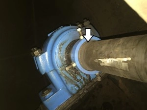
With little bracing supporting hundreds of square feet of thin, flexible sheet metal, significant vibration could easily be transmitted through the enclosure walls. With motor vibration measurements revealing low frequency pulsations at approximately 140 cpm, smooth flow may be difficult to achieve until testing can be completed on various damper and flow settings. Once proper flow requirements are determined, duct modification may be necessary.
Of course, at HI-TEK we’re balancing and vibration experts, not airflow engineers. But by conducting vibration analyses like this, we gain valuable knowledge about all kinds of vibrations, including those caused by airflow. What we really excel at, however, is rotating machinery vibration testing and balancing. So if you have rough-running rotating equipment, give us a call. We can help.